
ESP32를 살펴보고 있습니다.
나이가 먹어감에 따라 기억력이 점점(많이) 떨어집니다.
마치 단기 기억상실증에 걸린 것처럼 돌아서면 잊어 버립니다.
결국 정리하는 습관을 가져야 할 것 같습니다.
원래 정리 별로 못하던 성격이라 그냥 블로그에 정리 해 나가기로 합니다.
개인적인 정리내용이니 내용에 대해 이러쿵 저러쿵 하지 말아주셨으면 합니다. ^^
espressif/arduino-esp32
Arduino core for the ESP32. Contribute to espressif/arduino-esp32 development by creating an account on GitHub.
github.com
ESP32 Arduino 사이트 입니다.
ESP32, EWP8266, STM32 보드메니저 URL입니다.
https://raw.githubusercontent.com/espressif/arduino-esp32/gh-pages/package_esp32_index.json
https://arduino.esp8266.com/stable/package_esp8266com_index.json
https://github.com/stm32duino/BoardManagerFiles/raw/master/STM32/package_stm_index.json
Arduino IDE 에서 파일-> 환경설정-> 추가적인 보드 매니저 URLs 에 넣어주면 됩니다.

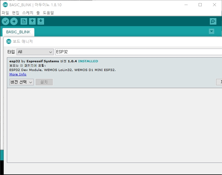
다음에 TOOL-> 보드 -> 보드메니저에서 Install해주면 됩니다.
예전에 비해 아주 간편해 졌습니다.
ESP32 으로 검색해서 인스톨 해줍니다.
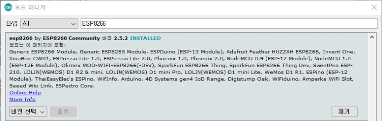
이왕 하는김에 ESP8266과 STM32도 인스톨 해줍니다.
같은 방법으로 json 파일 넣어준후 ESP8266 으로 검색해서 인스톨하고
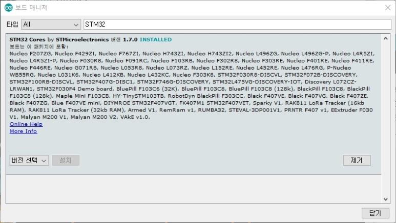
STM32 로 검색해서 인스톨하면 됩니다.
제가 요즘에 사용하는 것이 MEGA328, STM32, ESP8266, ESP32, nRF52 입니다.
nRF52만 추가로 설치 하면 Arduino 환경 설정은 끝이 날 것 같습니다.
ESP32 Arduino pinmap
Arduino프로그램에서 가장 처음 살펴봐야 할것은 핀맵입니다.
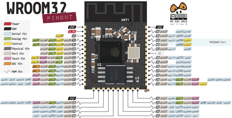
ESP32-WROOM-32D 핀맵입니다.
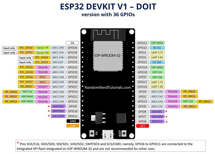
제가 사용하고 있는 개발KIT 핀맵 입니다.
*표시된 부분은 ESP32-WROBER모델에서는 내부에서 PSRAM용 인터페이스로 사용하기 때문에 사용하면 안됩니다.
ESP32 Peripherals
The ESP32 peripherals include:
18 Analog-to-Digital Converter (ADC) channels
3 SPI interfaces
3 UART interfaces
2 I2C interfaces
16 PWM output channels
2 Digital-to-Analog Converters (DAC)
2 I2S interfaces
10 Capacitive sensing GPIOs
위와 같은 기능을 가지고 있습니다.
하지만 내부 SPI Flash나 WROBER모델의 경우 PSRAM 인터페이스를 위해 핀들이 소모되어 절름발이나 사용할수 없는 펑션들이 생기게 됩니다.
이런점을 고려해서 작성된 GPIO 핀맵입니다.
GPIO Pinmap

Input only pins
GPIOs 34 to 39 are GPIs – input only pins.
These pins don’t have internal pull-ups or pull-down resistors.
They can’t be used as outputs, so use these pins only as inputs:
GPIO 34
GPIO 35
GPIO 36
GPIO 39
SPI flash integrated on the ESP-WROOM-32
GPIO 6 to GPIO 11 are exposed in some ESP32 development boards. However, these pins are connected to the integrated SPI flash on the ESP-WROOM-32 chip and are not recommended for other uses. So, don’t use these pins in your projects:
GPIO 6 (SCK/CLK)
GPIO 7 (SDO/SD0)
GPIO 8 (SDI/SD1)
GPIO 9 (SHD/SD2)
GPIO 10 (SWP/SD3)
GPIO 11 (CSC/CMD)
Capacitive touch GPIOs
The ESP32 has 10 internal capacitive touch sensors. These can sense variations in anything that holds an electrical charge, like the human skin. So they can detect variations induced when touching the GPIOs with a finger. These pins can be easily integrated into capacitive pads, and replace mechanical buttons. The capacitive touch pins can also be used to wake up the ESP32 from deep sleep.
Those internal touch sensors are connected to these GPIOs:
T0 (GPIO 4)
T1 (GPIO 0)
T2 (GPIO 2)
T3 (GPIO 15)
T4 (GPIO 13)
T5 (GPIO 12)
T6 (GPIO 14)
T7 (GPIO 27)
T8 (GPIO 33)
T9 (GPIO 32)
Analog to Digital Converter (ADC)
The ESP32 has 18 x 12 bits ADC input channels (while the ESP8266 only has 1x 10 bits ADC). These are the GPIOs that can be used as ADC and respective channels:
ADC1_CH0 (GPIO 36)
ADC1_CH1 (GPIO 37)
ADC1_CH2 (GPIO 38)
ADC1_CH3 (GPIO 39)
ADC1_CH4 (GPIO 32)
ADC1_CH5 (GPIO 33)
ADC1_CH6 (GPIO 34)
ADC1_CH7 (GPIO 35)
ADC2_CH0 (GPIO 4)
ADC2_CH1 (GPIO 0)
ADC2_CH2 (GPIO 2)
ADC2_CH3 (GPIO 15)
ADC2_CH4 (GPIO 13)
ADC2_CH5 (GPIO 12)
ADC2_CH6 (GPIO 14)
ADC2_CH7 (GPIO 27)
ADC2_CH8 (GPIO 25)
ADC2_CH9 (GPIO 26)
Digital to Analog Converter (DAC)
There are 2 x 8 bits DAC channels on the ESP32 to convert digital signals into analog voltage signal outputs. These are the DAC channels:
DAC1 (GPIO25)
DAC2 (GPIO26)
RTC GPIOs
There is RTC GPIO support on the ESP32. The GPIOs routed to the RTC low-power subsystem can be used when the ESP32 is in deep sleep. These RTC GPIOs can be used to wake up the ESP32 from deep sleep when the Ultra Low Power (ULP) co-processor is running. The following GPIOs can be used as an external wake up source.
RTC_GPIO0 (GPIO36)
RTC_GPIO3 (GPIO39)
RTC_GPIO4 (GPIO34)
RTC_GPIO5 (GPIO35)
RTC_GPIO6 (GPIO25)
RTC_GPIO7 (GPIO26)
RTC_GPIO8 (GPIO33)
RTC_GPIO9 (GPIO32)
RTC_GPIO10 (GPIO4)
RTC_GPIO11 (GPIO0)
RTC_GPIO12 (GPIO2)
RTC_GPIO13 (GPIO15)
RTC_GPIO14 (GPIO13)
RTC_GPIO15 (GPIO12)
RTC_GPIO16 (GPIO14)
RTC_GPIO17 (GPIO27)
PWM
The ESP32 LED PWM controller has 16 independent channels that can be configured to generate PWM signals with different properties. All pins that can act as outputs can be used as PWM pins (GPIOs 34 to 39 can’t generate PWM).
To set a PWM signal, you need to define these parameters in the code:
Signal’s frequency;
Duty cycle;
PWM channel;
GPIO where you want to output the signal.
I2C
The ESP32 has two I2C channels and any pin can be set as SDA or SCL. When using the ESP32 with the Arduino IDE, the default I2C pins are:
GPIO 21 (SDA)
GPIO 22 (SCL)
SPI
By default, the pin mapping for SPI is:
|
SPI |
MOSI |
MISO |
CLK |
CS |
|
VSPI |
GPIO 23 |
GPIO 19 |
GPIO 18 |
GPIO 5 |
|
HSPI |
GPIO 13 |
GPIO 12 |
GPIO 14 |
GPIO 15 |
Interrupts
All GPIOs can be configured as interrupts.
Strapping Pins
The ESP32 chip has the following strapping pins:
GPIO 0
GPIO 2
GPIO 4
GPIO 5 (must be HIGH during boot)
GPIO 12 (must be LOW during boot)
GPIO 15 (must be HIGH during boot)
These are used to put the ESP32 into bootloader or flashing mode. On most development boards with built-in USB/Serial, you don’t need to worry about the state of these pins. The board puts the pins in the right state for flashing or boot mode. More information on the ESP32 Boot Mode Selection can be found here.
However, if you have peripherals connected to those pins, you may have trouble trying to upload new code, flashing the ESP32 with new firmware or resetting the board. If you have some peripherals connected to the strapping pins and you are getting trouble uploading code or flashing the ESP32, it may be because those peripherals are preventing the ESP32 to enter the right mode. Read the Boot Mode Selection documentation to guide you in the right direction. After resetting, flashing, or booting, those pins work as expected.
Pins HIGH at Boot
Some GPIOs change its state to HIGH or output PWM signals at boot or reset. This means that if you have outputs connected to these GPIOs you may get unexpected results when the ESP32 resets or boots.
GPIO 1
GPIO 3
GPIO 5
GPIO 6 to GPIO 11
(connected to the ESP32 integrated SPI flash memory – not recommended to use).
GPIO 14
GPIO 15
Enable (EN)
Enable (EN) is the 3.3V regulator’s enable pin. It’s pulled up, so connect to ground to disable the 3.3V regulator. This means that you can use this pin connected to a pushbutton to restart your ESP32, for example.
GPIO current drawn
The absolute maximum current drawn per GPIO is 40mA according to the “Recommended Operating Conditions” section in the ESP32 datasheet.
ESP32 Built-In Hall Effect Sensor
The ESP32 also features a built-in hall effect sensor that detects changes in the magnetic field in its surroundings.
Wrapping Up
We hope you’ve found this reference guide for the ESP32 GPIOs useful. If you have more tips about the ESP32 GPIOs, please share by writing a comment down below.
정리하기 귀찮아 긁어와 정리 해 두었습니다.
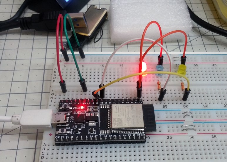
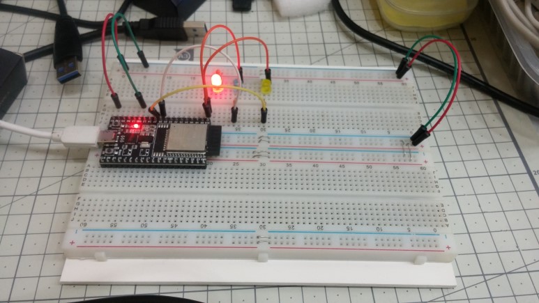
일단 LED 두개 달아서 Blink 테스트 해보았습니다.
쩝.. 입력 전용 GPIO에다 LED물려 놓고 안되어서 한참 삽질 했습니다.
결국 위 핀맵 정리하고나서야 입력전용이라는 사실을 알고 수정해서 동작 했네요.
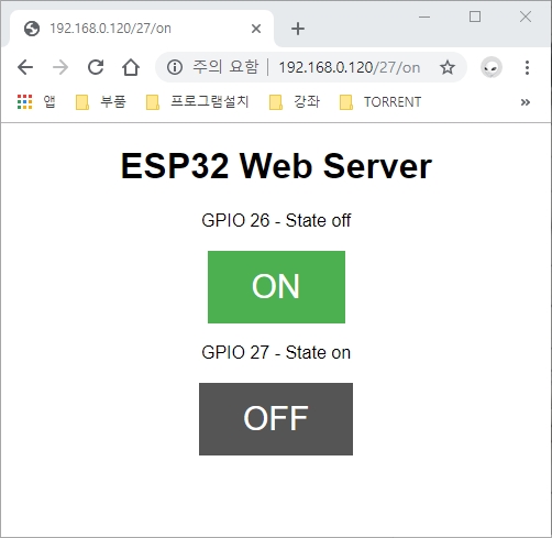
간단한 Web server 프로그램 올려서 Wi-Fi 연결이 잘되는지 확인해 보았습니다.
제가 Maker활동 외형제작을 위해 CNC나 3D프린터 , CAD/CAM과 같은 기구쪽으로 외도하기 시작한 2년전에 비해서 자료가 무척 많아 졌습니다.
그때는 자료가 없어서 무척 삽질을 했는데 지금은 자료가 많아 대충 찾아보면 널려 있네요.
물론 국내 자료는 거의 없습니다.
국내는 대부분 시작하는 부분자료 밖에는 없네요.
혹 시작하시는 분들 계시면 아예 해외자료 보고 하시는 것이 좋을 듯 싶습니다.
유튜브에서 검색해서 대충 하고 싶은 것 찾아 보시고 링크된 자료들 찾아보시면 훨씬 빨리 접근이 가능 할 것 같습니다.
Arduino IDE 폰트변경
Arduino IDE 폰트를 변경 했습니다.
주로 영문은 consolas를 많이 사용하는데 한글이 필요할 경우 consolas는 한글을 지원하지 않기 때문에 네이버에서 코딩용으로 배포하고 잇는 D2coding폰트로 바꾸었습니다.
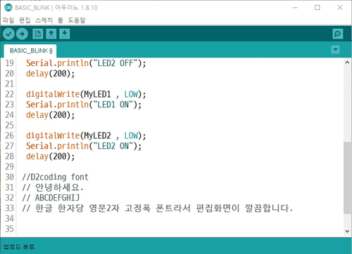
위와 같이 D2coding 은 한글 한자당 영문 2자인 고정폭 폰트입니다.
들여쓰기나 편집시 줄맞추기가 아주 편합니다.
변경하는 방법은
먼저 D2coding 폰트를 깔아줍니다.
naver/d2codingfont
D2 Coding 글꼴. Contribute to naver/d2codingfont development by creating an account on GitHub.
github.com
링크로 가서 하단의
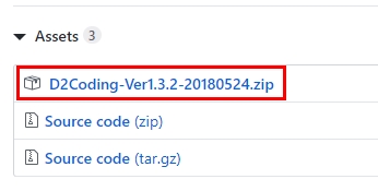
D2Coding-Ver1.3.2-20180524.zip을 받습니다.
압축 풀어서 깔아주면 됩니다.
다음은 Arduino 설정입니다.
Arduino IDE에서 파일--> 환경설정을 열어서
환경설정파일의 위치를 알아내 편집기로 엽니다.
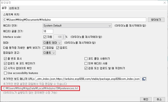
preferences.txt 입니다.
내용중에서 editor.font를 찾아서 D2Coding으로 바꾸어 줍니다.
"editor.font=D2Coding,plain,18"
참고로 사이즈는 짝수배로 해야 영문과 한글 비율이 1:2가 되는 군요.
아두이노의 한글 부분은 좀 골때립니다.
특히 IDE Editor에서 한글 코드가 3바이트 코드라 메세지 표시할 때 혼란을 주기도 합니다.
환경설정은 끝냈고 모듈이 커서 작은 빵보드는 불편해서 빵보드 2개를 붙여서 좀 크게 만들었습니다.
여기서 기본 펑션들 정리해서 동작 시험한후 문제 없으면 회로도 작업하고 PCB제작해서 커스텀 보드로 만들어나갈 생각입니다.
일단 먼저 OLED와 TFT LCD 두가지 라이브러리를 정리 해야 할 것 같습니다.
기존에 라이브러리들은 많지만 문제가 한글이 지원이 되지 않는 다는 것이지요.
저번에 Mega328 Arduino와 ESP8266 은 OLED용 한글은 정리 했었는데 어디에 저장되어 있는지 모르겠네요.
정리가 안되어서... 해놓고 다시 하고 해놀고 다시하고 악순환입니다.
이제는 정리좀 잘해가면서 해야 할 것 같습니다.
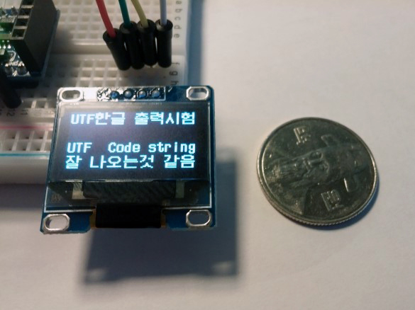
320 x 240 LCD에도 한글 출력이 가능하도록 라이브러리를 정리 해야 겠습니다.
Mega328의 경우 메모리가 작아 힘들었는데 ESP32는 나름 메모리가 많이 커져서 작업하기가 좋을 것 같습니다.
2.4" ILI9341 TFT LCD
시간나면 커스텀 LCD 라이브러리 제작해 볼까 하고 굴러다니던 LCD를 달아서 동작 시험을 해보았습니다.
2.4" 320 x 240 해상도를 가진 ILI9341을 콘트롤러로 사용한 TFT LCD 입니다.

#include "SPI.h"
#include "Adafruit_GFX.h"
#include "Adafruit_ILI9341.h"
Hardware SPI와 Adafruit_GFX, Adafruit_ILI9341 두가지 라이브러리를 사용했습니다.
일반적으로 쓸때는 문제가 없지만 가장 문제가 한글처리가 안된다는 점입니다.
이놈을 기반으로 확장을 할지 아니면 새로 작업을 할지 고민중입니다.
일단 동작은 잘하네요. 속도도 일반적으로 큰 문제 없을 정도의 속도가 나오는 것 같습니다.
시간내서 한번 정리 해 보면 될 것 같습니다.
날씨가 많이 쌀쌀해져서 사무실에 처음으로 난방을 가동 했습니다.
[ESP32] LCD 드라이버 선택(TFT_eSPI)
#스마트홈 시스템을 꾸며보려고 합니다. 거기에 사용할 컨트롤러로 ESP32를 정하고 관련 정리를 해나가고 있습니다. ESP32는 나름 내부 메모리가 크고 SPI Flash 혹은 SPI PSRAM을 부착 할수가 있어 메모리 용..
mytodoro.tistory.com
'IT관련 > ESP32' 카테고리의 다른 글
| [ESP32] JPG Image 출력 시험 (0) | 2019.11.13 |
|---|---|
| [ESP32] LCD 드라이버 선택(TFT_eSPI) (0) | 2019.11.09 |
| [ESP32] 부품도착 (0) | 2019.11.09 |
| [ESP32] 전용 DOWN LOADER (0) | 2019.11.09 |
| [ESP32] 자료정리 #1 (1) | 2019.11.09 |


댓글